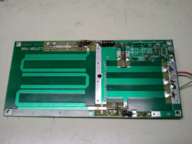
In the works - a 222 medium power ampifier using a Russian GI-7B tube - a GS35B amp, maybe for 6 meters, possibly HF - a weak signal source for 432, 1296, 2304, 3456 and 5760 - a 1 watt 2304 amplifier with 26 dB of gain - low noise preamps for 902, 2304 and 3456 - a 2 watt 3456 amplifier - a 1 watt 5760 amplifier - a legal limt + differential T tuner for HF (started) - stripline VHF/UHF directional coupler (started) - a 10 MHz reference system locked to GPS - a thermal watt meter (built but needs testing) - a 10 GHz transverter Pretty ambitious, huh? 2304 transverter kit This kit is a W1GHZ design, uses a 720 MHz LO board and the transverter board uses copper pipe cap filters, 2 on the LO chain, one common one for TX and RX and another one dedicated to the TX. LO drive is +7dBm, 144 MHz IF drive is 0 dBm and TX output is approximately +7 dBm. I used the simple RF detector board to tune the filters. The 3456 transverter looks identical, with the exception of a couple of components and tuning. These kits are a breeze to asssemble, but leave a bit to desire in the perfomance department as they are, a good low noise preamp and external TX amplifier will be needed to do any QSO's much past line of sight. 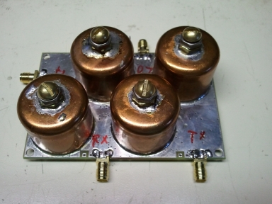
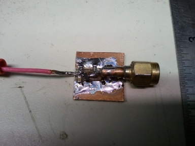
RF microve detector I aquired a set of low power transverters for 2.3, 3.4 and 5.7 GHz that still needed some work and wanted a simple way to check relative output. Wally, W9OBG, sent me a couple of home brew detectors that would not measure some of the lower levels I was wanting to look at, so I do some checking and purchased a few Agilent HSMS 2852, a zero bias detector diode. The package is a dual device SOT-23 pacakge, pretty small to work with. I created a slimple PC board that gave me room for the SMA input, a 50 ohm load, the SOT-23 diode package and a cap and resisitor. The larger board is one using simple hot carrier diodes. With 1 milliwatt at 50 MHz into the smaller detector using the zero bias diode, I get 220 mV DC out. The one using the larger hot carrier diodes only has 61 mV DC out. At levels much below 1 milliwatt, the hot carrier diodes do not produce any voltage, the 2852 produces a detectable voltage to well below -10 dBm. The circuit is very simple and could be built on a connector. The center pin of the connector has the 50 ohm load resistor to ground, one diode goes to ground and one in series with the output, a small cap, I used a 220 pF to filter the ripple and a small resistor to ground, i think I used a 68 K ohm. 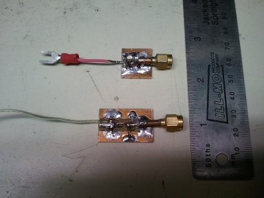
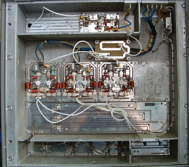
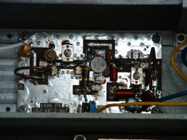
2 meter amp conversion project |